Design is a critical element in sheet metal processing, which visualizes the end result and serves as an engineering blueprint throughout the process. It is also a means of communication between designers, engineers, machinists, and fabricators across the sheet metal manufacturing industry, including companies like ProleanMFG.
Designing is not only about sketching the sheet metal part, illustrating shape, dimensions, geometrical features, and tolerances. Instead, it must be optimized for manufacturability, structural rigidity, assembly alignment, and cost reduction.
This article will discuss seven key sheet metal design guidelines.
1.Dimensioning
Dimension labelling is a sheet metal design that defines the shape, size, and orientation of a part & its features. It includes sheet metal flange length, bend line, bend angle, bend radius, sheet thickness, hole diameter, and other relevant sheet metal dimensions. Consequently, all dimensions should be labelled in a consistent unit of measurement.
- Ensure consistent orientation of bends and uniform wall thickness.
- When defining tolerances, consider the capabilities of the equipment and tooling you will use to fabricate the design later.
- Compensate for springback by overbending, taking into account the material type, thickness, and tooling.
2. Minimum Bend Radius
Bend radius is the radius of curvature formed by bending, measured from the inner surface of the sheet. You must consider the minimum bending radius to avoid cracking or deformation.
Minimum Bending Radius(R)= 1 to 1.5 x Sheet Thickness (t)
Moreover, you can always refer to the standard sheet metal bend radius chart or one provided by the fabricator. It allows you to choose the minimum bend radius value based on material type and sheet thickness.
3. Bend Relief, Bend Allowance, and Bend Offset
Add small cutouts (or notches) at the end of the bend lines as reliefs. They avoid stress concentrations and prevent material tearing and distortion.
Minimum width of Cutouts/Notches = Sheet thickness (t)
Maximum width of Cutouts/Notches = Sheet thickness (t)+ Bend radius(R)
Bend allowance refers to the compensation for the material length consumed by the bend due to compression and stretching. It helps to ensure the correct size of the flat sheet to fabricate the designed part.
Bending Allowance(BA)= Bend angle(θ ) x π 180 (R + K x t)
The bend offset is the deviation from the initial plane after bending, typically used in Z metal brackets and other related geometries. The offset planes should be parallel to each other.
4. Minimum Flange Length
Shorter flange lengths are challenging to bend, and they also impact the structural integrity of components. Therefore, you must maintain a minimum flange length. It depends on the ductility of materials. For instance, the minimum flange length for aluminum is lower compared to that of forming steel sheet.
Minimum Length of Flange ( for soft sheet metals) = 2 x thickness (t)
Minimum Length of Flange ( for hard sheet metals) = 4 x thickness (t)
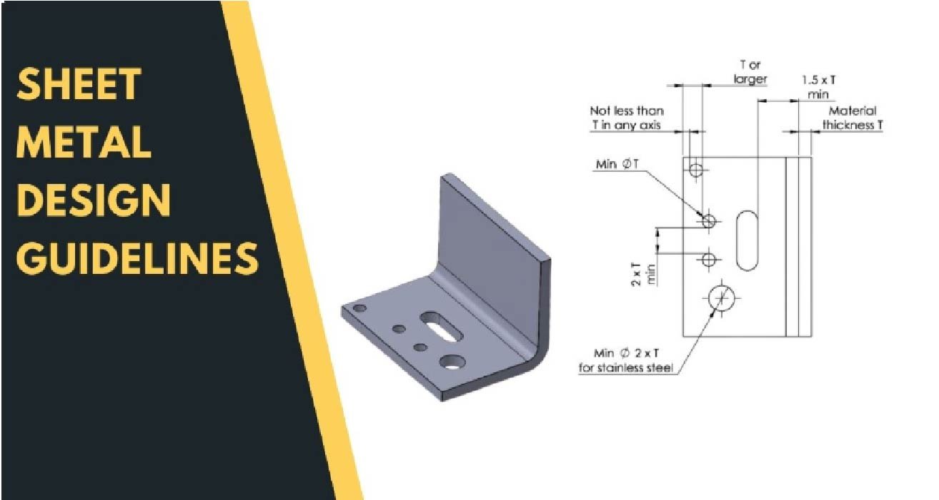
5. Hole Sizes
If you design with punching holes, there are specific rules related to their diameter, distance between two adjacent holes, edge-to-hole distance, etc. Improper size and location of holes can compromise strength and even lead to material failure.
Minimum Hole Diameter = 1.5 x thickness (can be slightly lower for soft metals)
Minimum Spacing of Two Adjacent Hole Centres = 2 x thickness (t) + Bend Radius (R)
Minimum Hole to Edge Distance = 3 x thickness (t)
6. Kerf, Curls, and Corner Fillets
Kerf is the material that is removed during the cutting of sheet metal using laser, plasma, or shear blades.
Laser cutting kerf= 0.080 mm to 0.45 mm
Next, curls are circular hollow rolls at the edge of sheet metal.
Minimum Curl Radius= 2 x sheet thickness(t)
Minimum Curl to Bend Distance= 6 x Curl Radius + sheet thickness(t)
Add fillets to the bend corners, which will finish and reinforce the sheet edges.
Fillet size= 0.5 x sheet thickness(t)
7. Features Near a Bend
If you are forming holes, cutouts, embossing, or other features, you must maintain a minimum spacing between them. It is essential to avoid material cracking and obtain good formability. Additionally, avoid placing fastener inserts and threads directly on the bend line.
Spacing between consecutive bend = 3 x sheet thickness(t)
Minimum Distance between bend and features= 2x sheet thickness(t) + Bend radius (R)
Conclusion
Overall, sheet metal design requires several considerations for DFM optimization and cost reduction. It includes choosing the right thickness, dimensioning of features, hole placing, bend parameter calculation, edge treatment, size allowance for forming operation, and many more. If you need a detailed consultation for sheet metal services, contact industry designers now.
FAQs
How Important is Material Thickness in Sheet Metal Design?
Sheet metal thickness is the most critical parameter in sheet metal design, as it defines strength, stiffness, springback, minimum bend radius, hole sizing, flange length, and other key characteristics.
What is the rule of thumb for sheet metal?
The rule of thumb in sheet metal is “ use the thinnest sheet metal gauge that meets the desired stiffness and determine other design variables based on that, such as bed radii, sizing of holes and features, and spacing of features.
What is the sheet metal rule?
Sheet metal rules refer to a set of design guidelines, including uniform thickness, avoiding sharp internal corners, bend radius, and allowance.